 (780) 669-9420

10 Best Gate Valves for Industrial Applications
Industrial facilities rely on valves to isolate pipelines, protect equipment, and support maintenance. A gate valve is often chosen for full-bore flow and dependable shutoff, not frequent throttling. The choice still depends on service conditions. Pressure, temperature, fluid chemistry, and operating frequency can change which design performs well.
Infrastructure reports show why careful selection matters. The U.S. Environmental Protection Agency’s 2023 Drinking Water Infrastructure Needs Survey estimates $625 billion in drinking-water investment needs over 20 years. The International Energy Agency’s World Energy Investment 2024 report projects global energy investment above $3 trillion in 2024, including about $2 trillion for clean-energy technologies and infrastructure. These figures describe broad infrastructure needs, not gate valve sales. That distinction matters.
This guide compares 10 gate valves for industrial applications across water treatment, power generation, process plants, and other demanding systems. It considers body and trim materials, pressure ratings, temperature limits, end connections, stem design, actuation, and relevant industry standards. A bronze valve may suit one line, while a corrosion-resistant alloy may be essential in another. Small details matter. No single model fits every plant, and product claims should be checked against current manufacturer data and site conditions. The rankings offer a practical starting point, not a substitute for engineering review. Even a well-specified valve can disappoint if installation or maintenance is overlooked.
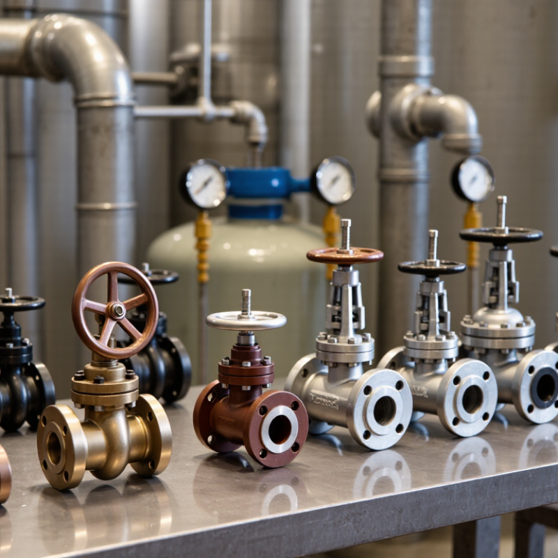
Gate Valve Fundamentals: Linear Shutoff, Flow Path, and Industrial Uses
10 Best Gate Valves for Industrial Applications
Gate Valve Fundamentals: Linear Shutoff, Flow Path, and Industrial Uses
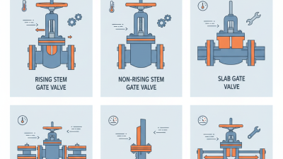
A gate valve controls flow by moving a wedge or slab in a straight line across the passage. Turning the handwheel raises or lowers the stem and gate. Fully open, the gate lifts clear of the flow path. This creates a relatively direct route with little obstruction. The valve is designed mainly for on-off service, not precise throttling. Leaving it partly open can cause vibration, wear, or damage to the seating surfaces.
Water-treatment lines, utility headers, and process piping use gate valves when reliable isolation is needed. Their straight-through flow path can suit larger pipelines where pressure loss matters. A practical selection mistake is to focus only on pipe size. Pressure, temperature, fluid properties, end connections, and operating frequency matter too. The details can be easy to overlook. Check the valve’s technical documentation and operating limits against actual service conditions.
Tips: Confirm the valve is fully open during normal flow. For maintenance, verify isolation using the site’s approved procedure; a closed valve may still leak. Consider access around the handwheel and stem, especially in crowded pipe racks. Selection is not always neat: installation space or infrequent operation may shape the choice as much as flow requirements.
10 Best Gate Valves for Industrial Applications - Gate Valve Fundamentals: Linear Shutoff, Flow Path, and Industrial Uses
| # | Valve configuration | Gate and flow path | Common industrial uses | Selection considerations |
|---|---|---|---|---|
| 1 | Solid wedge, rising stem | A solid wedge moves linearly between the seats. When fully open, the gate is lifted clear of the flow passage. | General-purpose isolation in water, utility, and process piping. | Rising-stem movement is visible, but requires vertical clearance. Best used fully open or fully closed, not for routine throttling. |
| 2 | Flexible wedge | A one-piece wedge has a shaped, flexible section that can accommodate small changes in seat alignment. | Steam and thermal-cycle services, subject to the valve’s material and pressure-temperature rating. | The flexible design can reduce binding from thermal expansion compared with a rigid wedge; correct installation and service conditions still matter. |
| 3 | Split wedge | Two-piece gate segments seat against the body seats and can adjust to some seat irregularities. | Isolation duties in selected oil, gas, and process services. | Check fluid cleanliness and the manufacturer’s allowable pressure, temperature, and leakage criteria; the segmented gate is not a substitute for proper sizing. |
| 4 | Parallel slide | Parallel gate plates move across the passage; the design relies on its seating arrangement rather than a wedging action. | Some steam, power-generation, and high-temperature isolation services. | Confirm that the specific design is suitable for the pressure, temperature, and operating cycle. “Parallel slide” designs vary by construction. |
| 5 | Knife gate | A thin, usually sharpened gate travels through the passage to help cut or clear fibrous and suspended material. | Pulp and paper, wastewater, mining, and slurry-handling lines. | Choose a design and seat suited to the solids, slurry concentration, and required shutoff. Many knife gate valves are not intended for high-pressure service. |
| 6 | Slab gate, through-conduit | A flat gate with a passage through it aligns with the pipeline bore when open, providing a straight-through flow path. | Pipeline isolation in oil and gas transmission and related services. | Check bore alignment, seat design, pressure class, and compatibility with the fluid and any solids. Pipeline designs may include specific sealing and cavity features. |
| 7 | Expanding gate | Gate segments expand against the seats at the end of travel; some designs provide sealing on both sides. | Selected pipeline and process isolation duties where the design’s bidirectional sealing capability is required. | Verify the specified sealing direction, pressure rating, and operating procedure. Bidirectional performance depends on the particular design and conditions. |
| 8 | Non-rising stem | The stem rotates without moving upward; the gate travels within the body as the valve opens or closes. | Water distribution, underground installations, and locations with limited overhead clearance. | Requires less vertical space, but stem position does not provide the same direct visual indication of gate travel as a rising stem. |
| 9 | Flanged-end gate valve | The body connects to mating pipe flanges; the internal gate design may be wedge, parallel, or another configuration. | Plant piping where bolted connections and planned access for maintenance are appropriate. | Match flange dimensions, facing, pressure class, and gasket requirements to the piping system. Allow space for installation and removal. |
| 10 | Actuated gate valve | An electric, pneumatic, or hydraulic actuator moves the gate linearly, often through a stem and drive mechanism. | Remote, automated, or high-cycle isolation in process plants and utility systems. | Size the actuator for operating thrust or torque, differential pressure, and duty cycle. Include suitable controls and position indication where needed. |
Gate valves are linear-motion isolation valves. When fully open, many designs provide a relatively unobstructed flow path; they are generally not recommended for routine throttling because partial opening can cause vibration, wear, and seat or gate damage. Final selection should be based on the fluid, pressure-temperature conditions, applicable standards, connection details, and required shutoff performance.
Related Posts
-
Apa Itu Gate Valve 7 Tips for Global Buyers?
-

Why Choose a 4 Gate Valve for Your Industrial Applications?
-
Why Choose a Gate Valve: Benefits and Applications in Modern Plumbing Systems
-
2026 Top Gate Valve Types for Your Industrial Applications?
-
Top Gate Valve Types Explained for Your Industrial Needs?
-

Top Tips for Sourcing Gate Valves at Canton Fair 139?