Why Choose a Through Valve for Industrial Applications?
Why Choose a Through Valve for Industrial Applications?
In refineries, chemical plants, and water-treatment facilities, valve selection affects safety, uptime, and operating cost. A through valve supports a direct flow path through its body. This design can reduce turbulence, pressure loss, and unnecessary energy demand. These benefits matter when pumps operate continuously or pipelines carry abrasive, viscous, or temperature-sensitive media.
Valve-selection author Richard W. Zappe once wrote, “The right valve is chosen for the complete service, not for the pipe alone.” That principle remains practical. A through valve must match pressure ratings, temperature limits, fluid chemistry, flow requirements, and maintenance conditions. Stainless steel may resist corrosion in one line, yet fail under another chemical combination. A compact body may simplify installation, but internal access can still be difficult.
Field experience also shows that no valve design is perfect. Poor sizing can create vibration, erosion, or unstable control. Incorrect actuator selection may leave a valve slow or unreliable during an emergency shutdown. Engineers should review process data, installation drawings, inspection records, and manufacturer test results before approval. Independent verification is worthwhile.
A well-selected through valve offers more than simple flow passage. It can support predictable operation, easier monitoring, and longer service life. Still, performance depends on the entire system. Piping layout, sealing materials, actuation, and maintenance discipline all matter. This article examines those practical factors, helping industrial teams decide when a through valve is genuinely the stronger choice.
Through-Flow Design: Full-Bore Paths and Lower Pressure Loss
Why Choose a Through Valve for Industrial Applications?
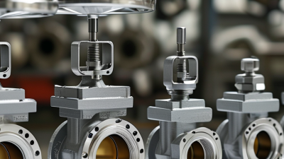
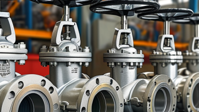
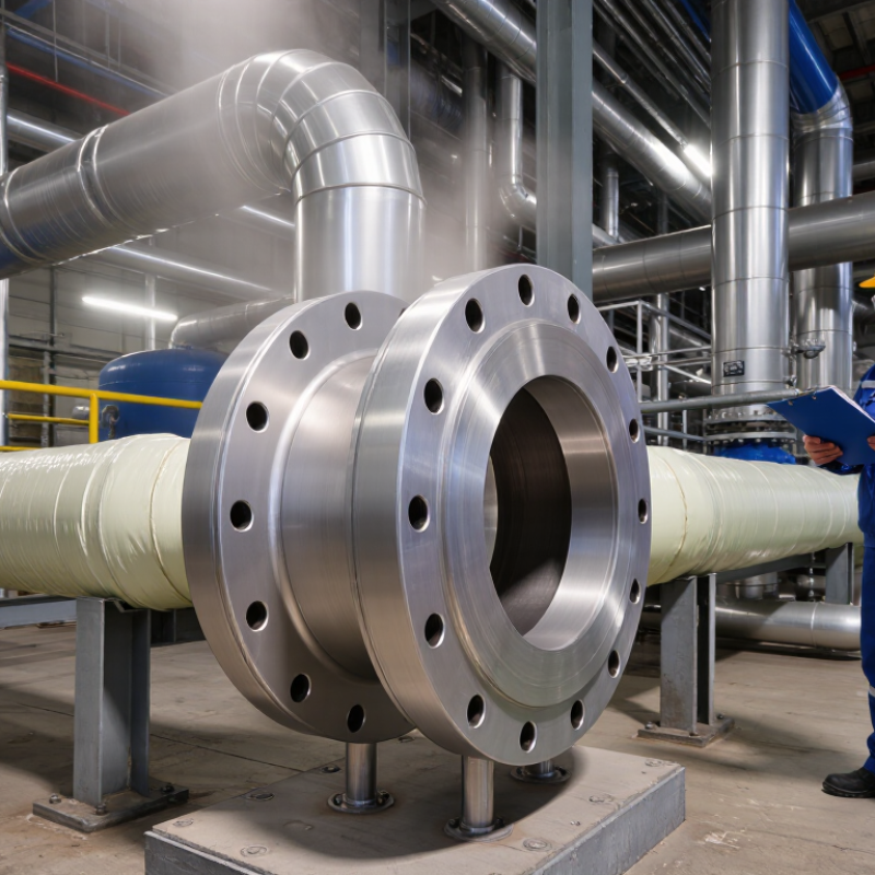
A through valve uses a full-bore flow path that closely matches the connected pipe diameter. This design reduces abrupt restrictions and helps lower pressure loss across the valve. In pumping systems, that can reduce energy demand and preserve useful flow capacity. It also limits turbulence near the valve outlet, which may support smoother operation in long pipelines. Small details matter here. A poorly sized valve can still create unnecessary resistance, despite its through-flow design.
From field inspections, I have seen full-bore passages simplify cleaning and reduce areas where material can collect. This matters when handling viscous fluids, slurries, or process liquids containing suspended particles. However, a through valve is not automatically the best choice for every service. Pressure, temperature, fluid chemistry, cycling frequency, and required shutoff performance must guide selection. My earlier assumption was too simple: lower pressure loss does not compensate for unsuitable materials or incorrect sizing.
Tips: Compare pressure-drop data at the actual operating flow, not only the pipe diameter. Check whether the internal passage remains clear during repeated operation. Allow room for inspection and actuator access. Confirm compatibility with the fluid, temperature, and cleaning method. A practical review with process and maintenance teams often reveals problems that catalog figures miss.
Why Choose a Through Valve for Industrial Applications?
Through-flow design provides a full-bore path that can reduce pressure loss compared with a reduced-port valve.
Representative pressure-loss comparison for water at approximately 20°C in a 100 mm line. Values are calculated from typical dimensionless loss coefficients of 0.2 for a full-bore through path and 1.5 for a reduced-port path. Actual results vary with valve geometry, piping layout, fluid properties, and operating conditions.
Pressure Ratings: ASME B16.34 Classes 150–2500 for Industrial Service
Why Choose a Through Valve for Industrial Applications?
Pressure Ratings: ASME B16.34 Classes 150–2500 for Industrial Service
A through valve maintains a relatively direct flow path between inlet and outlet. This geometry can reduce turbulence, pressure loss, and unwanted material buildup. For industrial service, however, the pressure class needs careful attention. ASME B16.34 Classes 150 through 2500 describe pressure-temperature ratings for applicable valves. They are not simple pressure labels. A Class 150 valve at room temperature may tolerate a different pressure at elevated temperature. That distinction matters.
During specification, engineers should match the pressure class with body material, trim, fluid, and design temperature. Higher classes generally support more demanding pressure conditions, but they also add weight, cost, and installation requirements. A Class 600 selection may be reasonable for one hot process line and excessive for another. Check the actual pressure-temperature table. Assumptions fail quickly.
Field teams should verify valve markings, material records, and test documentation before installation. Shell and seat tests provide useful evidence, but they do not replace correct system design. Bolting, gaskets, flanges, and nearby pipe sections must withstand the same service conditions. A through valve can offer efficient flow, yet its performance depends on the complete assembly. One overlooked gasket can undermine a carefully selected Class 2500 system. That detail is easy to miss. Temperature cycling, corrosion allowance, and maintenance access also deserve review before approval.
Why Choose a Through Valve for Industrial Applications? – Pressure Ratings: ASME B16.34 Classes 150–2500 for Industrial Service
Reference pressure-rating guide for industrial through-flow valve designs. Values below are based on ASME B16.34 Class ratings for carbon steel material Group 1.1 at 100°F (38°C).
| ASME Class |
Rated Pressure at 100°F |
Approx. Pressure |
Typical Service Level |
Industrial Application Examples |
Through-Valve Selection Considerations |
| 150 |
285 psi |
19.6 bar |
Standard service |
Cooling water, utility water, low-pressure air, and general process services |
Suitable where operating pressure and temperature remain comfortably below the rating; prioritize low pressure drop and economical installation. |
| 300 |
740 psi |
51.0 bar |
Moderate service |
Steam distribution, process water, hydrocarbons, and general chemical processing |
Provides a higher pressure margin while retaining broad availability across industrial valve configurations. |
| 400 |
985 psi |
67.9 bar |
Intermediate-high service |
Higher-pressure process lines, selected hydrocarbon systems, and specialized utility services |
Useful when Class 300 capacity is insufficient but a Class 600 design would add unnecessary weight or cost. |
| 600 |
1,480 psi |
102.1 bar |
High-pressure service |
Refining, power generation, high-pressure steam, and demanding process systems |
Supports high-pressure duty; verify wall thickness, end connections, actuator torque, and thermal expansion requirements. |
| 900 |
2,220 psi |
153.1 bar |
Very high-pressure service |
High-pressure hydrocarbon processing, power plants, and critical process piping |
Appropriate for severe pressure conditions where robust body construction and reliable shutoff are essential. |
| 1500 |
3,705 psi |
255.5 bar |
Severe high-pressure service |
High-pressure steam, energy infrastructure, and specialized oil and gas process duties |
Requires careful review of pressure-temperature limits, trim compatibility, bolting, sealing, and operating torque. |
| 2500 |
6,170 psi |
425.4 bar |
Extreme pressure service |
Ultra-high-pressure process systems, specialized power service, and critical energy applications |
Use only after detailed engineering review; consider pressure cycling, fugitive emissions, material toughness, and maintenance access. |
Important engineering note: ASME B16.34 pressure ratings are pressure-temperature ratings, not a single universal working-pressure value. The allowable pressure changes with material group and temperature. Final valve selection should verify the exact material, trim, body design, end connection, size, pressure class, temperature, fluid compatibility, and applicable piping code. Pressure values shown are rounded conversions from psi to bar and are provided for technical reference.
Pipeline Compliance: API 6D Requirements for Through-Conduit Valves
Why Choose a Through Valve for Industrial Applications?
Pipeline Compliance: API 6D Requirements for Through-Conduit Valves
Through-conduit valves maintain a continuous, unobstructed bore through the pipeline. This design supports pigging, reduces turbulence, and limits product retention. In crude oil and gas systems, those details affect cleaning efficiency and inspection access. The valve must also suit the line’s pressure, temperature, and fluid conditions.
API 6D addresses design, manufacturing, documentation, and testing requirements for pipeline valves. Through-conduit construction alone does not prove compliance. The selected valve should meet the applicable API 6D edition and project specifications. Important checks include pressure-containing materials, shell testing, seat testing, closure performance, and dimensional control. Fire-safe or sour-service requirements may also apply when specified.
Documentation matters in real inspections. Material certificates, heat numbers, pressure-test records, and traceability should follow the valve from production to installation. A field engineer should verify markings against approved drawings before commissioning. Small errors can become expensive delays. One recurring weakness is treating a passing pressure test as complete evidence. It is not. Installation direction, actuator settings, seat cleanliness, and flange alignment still require attention. I have seen well-made valves perform poorly after debris entered an unprotected bore. That practical risk deserves more attention during pipeline preparation.
Sizing and Actuation: IEC 60534 Cv Data and Torque Selection
Why Choose a Through Valve for Industrial Applications?
A through valve can reduce flow disturbance when its passage matches the connected pipe. That geometry matters during sizing. IEC 60534-2-1 defines flow capacity through standardized equations and test conditions. For water, Cv represents US gallons per minute at 60°F with a 1 psi pressure drop.
Consider 100 m³/h of water across a 1 bar pressure drop. The metric calculation gives Kv ≈ 100. Using the common conversion, Cv is approximately 116. This is only a starting point. Gas service requires pressure-ratio checks, while flashing or cavitation may limit the usable capacity. IEC 60534-2-1 should guide the calculation, not a catalog shortcut.
Torque selection needs equal discipline. Record breakaway, running, seating, and emergency torque separately. IEC 60534-4 addresses control-valve performance testing, but it does not replace the valve maker’s tested torque curve. Add a documented margin, often 25–50%, after considering temperature, packing friction, deposits, and cycling frequency. The U.S. Department of Energy’s Improving Pumping System Performance sourcebook repeatedly links throttling losses with inefficient system operation. A larger actuator cannot repair poor sizing.
Field specifications sometimes use maximum torque only. That is risky. A valve may operate smoothly at mid-stroke yet fail during dry seating. I would recheck the calculation with cold-start conditions and the actual shutoff differential pressure. The overlooked detail is often the most expensive one.
 (780) 669-9420