

What Are the Top RF Amplifier Types in 2026?

In 2026, choosing an RF Amplifier is less about naming one universal winner and more about matching its design to the signal, frequency, and operating conditions. A low-noise amplifier at a receiver’s input has a different job from a high-power stage feeding an antenna. Small details matter: bandwidth, heat, supply voltage, and even the layout of a board can change real-world performance.

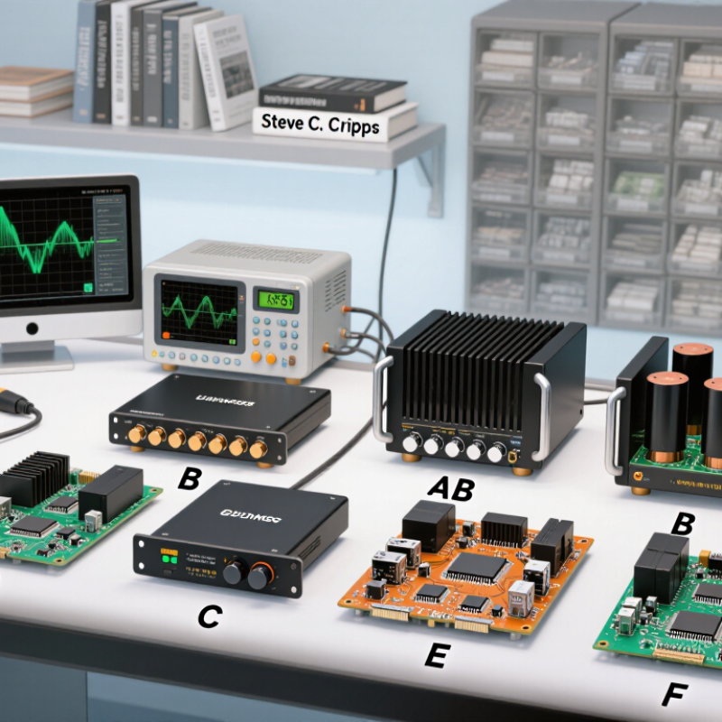
RF amplifier authority Steve C. Cripps has written extensively on power-amplifier design. A useful editorial paraphrase of a principle reflected in his work is: “Efficiency, linearity, and output power must be designed as trade-offs.” This is not a verbatim quotation. It captures why amplifier classes cannot be ranked by a single specification.

The guide explores Class A, B, AB, and C designs, alongside switching and tuned approaches such as Class D, E, and F. It also considers Doherty architectures, broadband amplifiers, low-noise models, and power stages built with GaN or LDMOS devices. Each has a place. None is ideal everywhere. A Class AB unit may offer a practical balance, while a Doherty design can suit demanding power-efficiency needs. But results depend on frequency, modulation, load, and implementation—not labels alone.

Look beyond headline output power. Compare gain, noise figure, bandwidth, linearity, efficiency, and thermal behavior. Check the test conditions, too. A tidy ranking can mislead; real installations are less tidy. This overview provides a grounded starting point for comparing leading RF Amplifier types in 2026 and deciding which trade-offs deserve closer attention.
What Are the Top RF Amplifier Types in 2026?

What RF Amplifiers Are and How They Work

An RF amplifier increases the power of a radio-frequency signal while preserving useful information carried by its changing waveform. It may sit between an antenna and a receiver, or near a transmitter’s output. The input can be tiny, sometimes only a few microvolts. The amplifier uses energy from its power supply to produce a stronger version of that signal.

Gain describes how much the signal grows. But more gain is not always better. Excessive amplification can add noise, distort peaks, or make nearby signals interfere. That matters. Engineers also consider frequency range, impedance matching, linearity, and stability. A mismatch at a connector can reflect energy instead of passing it along, while poor thermal design can cause performance to drift as components warm up.

Different RF amplifier designs suit different jobs. Low-noise amplifiers help preserve weak incoming signals; power amplifiers deliver stronger signals toward an antenna; driver stages provide an intermediate boost. These are functional categories, not a universal ranking. In a real circuit, the best choice depends on the signal level, bandwidth, and operating conditions. A clean block diagram can make the design look simple. It rarely shows every trade-off, and even a carefully measured setup may behave differently after cables or loads change.

What Are the Top RF Amplifier Types in 2026?

RF amplifier classes are commonly distinguished by how long their active device conducts during each signal cycle.

How to read this chart: Class A conducts for 360° and Class B for 180°. Class AB conducts for more than 180° and less than 360°; Class C conducts for less than 180°. The chart shows each class’s upper boundary, not a measured efficiency or a ranking. Actual RF amplifier performance depends on circuit design, frequency, and operating conditions.

The Main Types of RF Amplifiers in 2026

In 2026, RF amplifier types are easiest to understand by the job they perform. Low-noise amplifiers (LNAs) sit near an antenna or sensor. They strengthen weak signals while adding as little noise as practical. A fraction of a decibel can matter. Power amplifiers (PAs) drive the output stage, delivering signal power to a load or transmission path. Driver amplifiers bridge small-signal stages and a PA when one stage cannot provide enough clean gain. Heat matters.

Another useful distinction is bandwidth. Broadband amplifiers cover a wide frequency range, while narrowband designs focus on a smaller band and may offer higher gain or selectivity. Variable-gain amplifiers help systems adjust signal levels as conditions change. Operating classes describe a different feature: how the output device conducts. Class A and AB designs are common when linearity matters; Class C can improve efficiency in suitable constant-envelope applications, but it is not universal. Switching classes, such as D or E, suit particular high-efficiency designs. Trade-offs are real. Output power, noise figure, bandwidth, stability, and heat need to be checked together. Datasheet conditions may not match a real circuit, so bench measurements still matter.

What Are the Top RF Amplifier Types in 2026? – The Main Types of RF Amplifiers in 2026

Common RF amplifier types differ by their role, bandwidth, power level, and circuit architecture. These categories can overlap: for example, a Doherty amplifier is a power-amplifier architecture, while Class AB describes an operating class.

Amplifier type Primary role Typical applications Defining characteristic Main advantage Key trade-off
Power amplifier (PA) Raises a transmit signal to the power needed by an antenna or other load. Wireless infrastructure, radar, satellite links, and radio transmitters. Designed around output power, efficiency, linearity, and thermal limits. Provides the transmit power required by the system. Higher output power can increase heat, power consumption, and distortion.
Low-noise amplifier (LNA) Amplifies weak signals, commonly near a receiver input. Receivers for communications, navigation, radio astronomy, and radar. Prioritizes low added noise while providing useful gain. Helps preserve sensitivity to weak incoming signals. Strong nearby signals can cause compression or intermodulation.
Driver amplifier Supplies the signal level needed to drive a later amplifier stage. Transmit chains, test equipment, and multi-stage RF systems. Balances gain, bandwidth, and output capability for the following stage. Improves signal-level control between system stages. Adds its own noise, distortion, power use, and design complexity.
Variable-gain amplifier (VGA) Adjusts gain electronically in response to system conditions or a control signal. Receiver gain control, measurement systems, and signal-processing chains. Provides a controllable gain range, often for automatic gain control. Helps accommodate signals that vary in strength. Gain changes may affect noise, linearity, or signal accuracy.
Broadband amplifier Amplifies signals across a wide frequency range without retuning for each frequency. Laboratory instruments, multiband radios, and wideband communications. Designed for useful gain and stability over a broad bandwidth. Supports multiple frequencies or bands with one amplifier stage. Maintaining flat gain, matching, and stability over a wide range can be challenging.
Narrowband amplifier Amplifies signals within a limited frequency band. Channel-specific transmitters, receivers, and tuned RF stages. Uses frequency-selective design or matching optimized for a target band. Can offer efficient, well-controlled performance in its intended band. Usually requires retuning or a separate stage for another band.
Distributed amplifier Combines contributions from multiple active devices along transmission-line structures. Wideband microwave and millimeter-wave systems, including instrumentation. Transmission lines help extend bandwidth beyond that of a single-stage design. Can provide broad bandwidth and useful gain at high frequencies. May require more circuit area and power than simpler designs.
Doherty power amplifier Improves power efficiency in transmitters operating with varying signal levels. Cellular base stations and other communication transmitters with high peak-to-average signal levels. Uses carrier and peaking amplifier paths that contribute differently as output power changes. Can improve efficiency at power levels below peak output. Requires careful design of load modulation, bandwidth, and signal alignment.
Switch-mode PA (for example, Class E or F) Converts DC power into RF output using switching device operation. Selected transmitters where high efficiency is a priority and the signal and frequency suit the design. Uses circuit waveforms and harmonic terminations to reduce device power loss. Can achieve high efficiency under appropriate operating conditions. Output filtering, tuning, and linearity requirements can limit practical use.

How RF Amplifier Types Differ in Performance

RF amplifier types differ most in efficiency, linearity, noise, and usable bandwidth. A low-noise amplifier protects weak signals near the receiver input, where even a small noise increase can obscure detail. Power amplifiers focus on delivering stronger output. Class A designs usually offer good linearity, but waste more energy as heat. Class AB balances efficiency and signal quality for many practical transmitters. Class C can be efficient, though its distortion makes it unsuitable for some amplitude-sensitive signals. No type wins every test.

Topology matters too. A narrowband amplifier can provide high gain around a chosen frequency, while a broadband design covers a wider range with possible trade-offs in gain or matching. Check performance across the full operating band, not just at its center. Also compare output compression, stability, and thermal behavior under realistic loads. I’ve seen a tidy bench result change once cables and enclosures were added. Small details matter.

Tips: Match the amplifier to the signal and duty cycle. Measure gain, noise figure, and output power at the intended frequency. Keep an eye on temperature. If readings disagree, inspect the setup before blaming the circuit; measurement errors are easy to overlook.

Where Each RF Amplifier Type Is Used

Where an RF amplifier sits in the signal chain often matters more than its label. Low-noise amplifiers strengthen faint signals at receiver inputs, such as signals arriving at a satellite dish or a cellular antenna. Power amplifiers drive transmitters in base stations, handheld radios, and radar equipment. Driver amplifiers sit between them, adding enough gain to feed a final power stage. Small differences matter: a few decibels of gain can affect receiver sensitivity or transmitter output.

The GSMA’s Mobile Economy 2025 projects 5.5 billion 5G connections by 2030. That growth provides context for demand across phones, network radios, and indoor coverage systems, though it does not predict which amplifier design each system will use. Class A and AB designs suit signals needing good linearity, while Class E and F designs can improve efficiency in suitable narrowband transmitters. Broadband amplifiers also appear in lab test equipment, where engineers need a clean, wide frequency range. A tidy category chart can still mislead; bandwidth, heat, and signal distortion shape real choices.

Tips: Match the amplifier to its job. Check frequency range, gain, noise figure, output power, and linearity. For a receiver, noise figure is crucial. For a transmitter, measure heat under realistic load conditions. Datasheets rarely tell the whole story. Test the finished signal path.

How to Choose an RF Amplifier for a Specific Application

Choosing an RF amplifier begins with the signal path, not the highest gain on a datasheet. A receiver near a weak antenna may need a low-noise amplifier, where noise figure matters more than raw output power. A transmitter usually needs a power amplifier sized for its required output, bandwidth, and duty cycle. Driver amplifiers sit between stages. Small details matter. Check operating frequency, impedance, gain flatness, and heat at the actual enclosure temperature.

For modulated signals, compare output back-off, error vector magnitude, and adjacent-channel leakage—not just saturated power. A narrowband design may offer better efficiency, while a broadband amplifier can simplify multi-frequency testing but may trade away gain or linearity. 3GPP TR 38.913 lists IMT-2020 peak-rate targets of 20 Gbit/s downlink and 10 Gbit/s uplink. These are system-level targets, not amplifier specifications, but they underline why linearity and bandwidth deserve attention. A frequent design trap is choosing from headline figures before checking the waveform and load.

Tips: Test with the real signal, cable, and antenna load. Measure gain, compression, and temperature after warm-up. If the results are close to a limit, leave more margin; lab conditions rarely match the final installation.

×
img

    Contact Info

    Phone number

    661-392-8948

    Address info

    3451 Pegasus Drive, Bakersfield, CA USA