
7 Tips for Choosing the Right Relay Transmitter

Choosing the right Relay Transmitter can determine whether an industrial control system runs smoothly or produces confusing faults. A transmitter may look compact, yet its signal range, switching capacity, response time, and environmental rating matter greatly. In a factory cabinet, one incorrect specification can cause intermittent alarms, delayed machine feedback, or unnecessary maintenance visits. Small details matter.

This guide presents seven practical tips for making a more reliable choice. It examines application requirements, electrical compatibility, communication protocols, installation conditions, safety features, maintenance needs, and total ownership cost. These points reflect common engineering practices and real selection challenges, not only product descriptions. I have seen teams focus on purchase price and overlook humidity, vibration, or terminal access. That decision often becomes expensive later. Check the datasheet carefully. Then question it.

A dependable Relay Transmitter should match the connected equipment and the people maintaining it. Look for clear wiring diagrams, verified ratings, traceable test information, and support from an established manufacturer. Independent certifications can strengthen confidence, but they should still match your actual application and region. No single model fits every system. A device suitable for a clean laboratory may fail in a dusty production area. Even experienced technicians can miss this difference. The final choice deserves measured comparison, realistic testing, and a willingness to reconsider an attractive specification. Reliability is built through details, not promises.
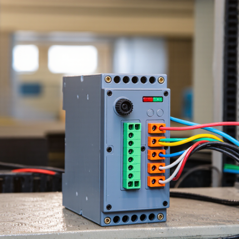
7 Tips for Choosing the Right Relay Transmitter

Define the Relay Transmitter’s Role in Your Control System

7 Tips for Choosing the Right Relay Transmitter

Define the Relay Transmitter’s Role in Your Control System

Before comparing specifications, define what the relay transmitter must do. It may monitor a pressure switch, isolate a sensor, or trigger an alarm circuit. These roles require different input ranges, output contacts, and response times.

That distinction matters.

Map the signal path on paper. Show the field device, relay transmitter, controller, and final load. Then record the expected voltage, current, switching frequency, and control distance. A relay rated for a small signal may fail when connected to a motor contactor. Check the load type, not only the nominal current. Inductive loads can create damaging electrical spikes.

In practical panel reviews, I look for three details: isolation, failure behavior, and maintenance access. Galvanic isolation can protect the controller from field-side faults. A normally open contact may be safer than a normally closed contact, depending on the alarm strategy. Confirm this choice with the system’s safety requirements. Keep it measurable.

Environmental conditions also shape the correct choice. Note cabinet temperature, humidity, vibration, dust, and available mounting space. A compact unit may fit neatly but leave no room for wiring or testing. I have seen clean specifications hide awkward terminals and unclear status indicators. That mistake is easy to repeat.

Choose a transmitter that supports clear diagnostics and documented testing. Verify terminal markings, wiring diagrams, and replacement procedures before installation. Ask whether a technician can test the relay without stopping the entire process. Small details matter. A technically suitable device can still be a poor control-system fit.

Match Signal Types, Ranges, and Communication Requirements

7 Tips for Choosing the Right Relay Transmitter
Tip one:
Identify the input signal before comparing models. A 4–20 mA loop needs different conditioning from a 0–10 V sensor. Thermocouples and RTDs also require correct compensation.
Tip two:
Confirm the output type. Choose relay contacts for simple alarms, analog outputs for control loops, or digital communication for connected systems.
Tip three:
Check the operating range, not only the nominal range. A transmitter measuring 0–100°C may perform poorly near 0°C.
Tip four:
Compare accuracy, resolution, and response time together. A precise device can still react too slowly for a fast process.
Tip five:
Require electrical isolation when ground loops or voltage differences may appear. Isolation can protect controllers and reduce unstable readings. I have seen commissioning teams overlook this detail. It becomes expensive later.
Tip six:
Match the communication protocol to the existing network. Modbus RTU, Modbus TCP, and other industrial protocols have different wiring and diagnostic requirements. A 2024 Industrial Network Market Shares report estimated industrial Ethernet at 71% of new industrial network nodes, showing why network compatibility deserves attention.
Tip seven:
Verify environmental ratings, terminals, and configuration tools. Dust, vibration, humidity, and cabinet temperature can change field performance. The 2024 World Robotics report recorded 541,302 industrial robot installations worldwide in 2023, increasing demand for dependable signal links. Still, reports cannot replace a site survey. Measure cable length, interference, spare channels, and maintenance habits before ordering. Small omissions matter.

Evaluate Isolation, Accuracy, Response Time, and Load Capacity

7 Tips for Choosing the Right Relay Transmitter

Evaluate Isolation, Accuracy, Response Time, and Load Capacity

Check the isolation rating between input, output, and power circuits. Strong galvanic isolation helps prevent ground loops and protects sensitive control equipment. Examine the test voltage, insulation resistance, and installation category. A high rating alone does not guarantee safe field performance.

Measure accuracy across the expected temperature range, not only at room temperature. Review offset, linearity, repeatability, and long-term drift. A transmitter may appear precise during commissioning but shift after months of vibration and heat. I have seen this mistake create unnecessary calibration work. Allow enough headroom for sensor error and wiring resistance.

Compare response time with the process requirement. A fast transmitter is useful for pressure changes, but excessive speed can expose electrical noise. Check whether the specification uses a step response, filter setting, or signal bandwidth. Ask how the device behaves during startup and signal loss. Small details matter. Match the output load capacity to the receiving controller, indicator, or recorder. Confirm voltage drop, loop resistance, and current limits under worst-case conditions. Do not rely on typical values. Review the power budget, enclosure space, terminal quality, and service access. Test one complete signal path before purchasing in quantity. This practical check often reveals grounding or loading problems that datasheets cannot show.

7 Tips for Choosing the Right Relay Transmitter

Compare the practical importance of isolation, accuracy, response time, and load capacity when selecting a relay transmitter. The weighting shown is a general engineering starting point and should be adjusted to match the application.

Isolation — 30%
Check the rated isolation voltage and test voltage. A common industrial range is approximately 1.5–4.0 kVrms, depending on installation and safety requirements.
Accuracy — 30%
Confirm accuracy as a percentage of span. Typical signal-conditioning requirements may range from ±0.1% to ±0.5% of span.
Response Time — 20%
For fast control or protection circuits, response times around 5–20 ms may be important. Slower processes may tolerate longer delays.
Load Capacity — 20%
Verify the output rating against the connected relay, actuator, or load. Example industrial requirements may range from 0.5–2.0 A.

Tip: Also verify input and output signal compatibility, wiring method, environmental rating, response behavior, and the required safety standard before final selection.

Check Environmental Ratings, Installation Methods, and Safety Standards

7 Tips for Choosing the Right Relay Transmitter

Environmental ratings should match the actual installation site, not the product catalogue alone. IEC 60529 defines IP54 as protection against limited dust and water splashes. IP65 provides dust-tight protection and resistance to water jets. A dusty control cabinet near a compressor may need more protection than a clean indoor panel. Heat matters too. Check the relay transmitter’s operating temperature, humidity range, vibration tolerance, and chemical exposure limits. A rating is not a guarantee.

Installation method affects reliability and maintenance time. DIN-rail mounting suits compact control cabinets and supports faster replacement. Panel mounting can provide stronger mechanical support, especially where vibration is present. Leave enough clearance for wiring bends and heat release. Confirm terminal direction before ordering. This small detail is often missed. It can turn a ten-minute installation into an awkward afternoon.

Safety standards deserve careful verification. IEC 60947-5-1 addresses low-voltage control circuit devices, while IEC 60255 covers protection and measurement equipment requirements. Select models with clear insulation, creepage, clearance, and terminal specifications. The U.S. Bureau of Labor Statistics recorded 145 fatal occupational injuries involving electricity in 2022. That figure reinforces the need for isolation, correct fusing, grounding, and documented testing. Installation should follow local electrical rules and the manufacturer’s instructions. I would still recheck every assumption, especially when the relay operates beside high-energy equipment.

Compare Configuration Options, Maintenance Needs, and Total Cost

7 Tips for Choosing the Right Relay Transmitter

Compare Configuration Options, Maintenance Needs, and Total Cost

Match the transmitter’s input range to the sensor, not merely the equipment label. A 24-volt supply may look standard, yet voltage variation can affect signal stability. Check terminal spacing, enclosure size, and communication options before installation. Select adjustable filtering when nearby motors create electrical noise. Keep the wiring practical.

Review how technicians will configure the unit. A clear display can reduce errors inside a crowded control panel. Remote settings may save travel time, but they also require secure access controls. Confirm alarm functions, diagnostic records, and calibration support. These details matter during a 2 a.m. fault.

Calculate the full cost over its service life. Include purchase price, engineering hours, spare units, calibration tools, energy use, and planned downtime. Ask how often maintenance is required and whether replacement terminals are available. I once underestimated labor because the installation looked simple on paper. That mistake changed the project budget. The cheapest option can become expensive after repeated resets and site visits. Compare documented test results, service procedures, and technical support quality. A short trial in the actual panel may reveal heat buildup, awkward access, or signal drift. Leave room for uncertainty.

7 Tips for Choosing the Right Relay Transmitter - Compare Configuration Options, Maintenance Needs, and Total Cost

Tip Configuration Option Typical Signal and Output Best-Fit Application Setup Requirements Typical Maintenance Expected Service Life Indicative Installed Cost* Main Trade-Off
1 Select the correct relay technology Electromechanical contacts; suitable for AC or DC switching within the rated load General-purpose alarms, interlocks, and infrequent switching Basic wiring and contact-rating verification; normally no software Inspect terminals and contacts; replace when contact wear or pitting appears 5–15 years, application dependent US$40–150 Low initial cost, but mechanical wear limits switching life and speed
2 Match switching frequency and load type Solid-state relay; AC or DC output selected for resistive, inductive, or motor loads Fast, repetitive switching where silent operation is important Confirm leakage current, heat dissipation, surge rating, and load compatibility Check heat sink, enclosure temperature, wiring torque, and leakage-related behavior 8–20 years with correct thermal design US$70–250 Long switching life, but heat and off-state leakage must be managed
3 Choose the right configuration method Fixed-function relay transmitter with preset input and output ranges Stable installations with standardized signals and repeatable operating conditions DIP switches or jumpers; calibration typically performed during commissioning Periodic functional test and terminal inspection; minimal software support required 10–20 years in controlled environments US$80–250 Simple and economical, but less flexible if process requirements change
4 Consider programmable flexibility Configurable transmitter supporting common analog inputs and relay, transistor, or analog outputs Mixed-signal systems, retrofit projects, and applications likely to be modified USB, keypad, or configuration software; parameter backup is recommended Verify configuration, firmware records, calibration, and alarm operation annually 8–15 years, depending on environment US$180–600 Higher purchase price, but fewer spare types and lower changeover cost
5 Verify isolation and signal integrity Galvanically isolated input/output channels, commonly used with 4–20 mA or discrete signals Long cable runs, different ground potentials, and electrically noisy environments Confirm isolation rating, loop power, burden, polarity, and electromagnetic compatibility Inspect shielding and grounding; test signal accuracy and isolation during scheduled shutdowns 10–20 years with suitable surge protection US$150–500 Improves reliability, but adds cost and requires careful wiring practices
6 Check environmental and safety requirements Industrial or safety-rated unit with defined temperature, vibration, enclosure, and failure-response ratings Process equipment, machinery protection, and installations requiring documented risk controls Review certifications, ambient limits, creepage, clearance, and fail-safe behavior Documented proof tests, visual inspection, and replacement based on the site safety plan 10–20 years; safety proof interval varies US$300–1,000 Higher total cost, justified where personnel or equipment risk is significant
7 Compare total cost of ownership Modular, socketed design with replaceable relay or plug-in electronics Sites prioritizing rapid replacement, spare-parts control, and reduced downtime Allow space for access; label wiring and retain configuration and test records Functional test, socket inspection, spare-unit rotation, and periodic terminal retorque 8–15 years, with replaceable modules US$120–450 May cost more initially, but can reduce labor, downtime, and inventory complexity

*Indicative installed-cost ranges are general planning estimates in USD for one channel, including basic wiring and commissioning. Actual cost depends on load type, hazardous-area requirements, enclosure, labor rates, certification, quantity, and site conditions.

×
img

    Contact Info

    Phone number

    661-392-8948

    Address info

    3451 Pegasus Drive, Bakersfield, CA USA