2026 Best 555 IC Timer Circuit for Buyers?
A 555 Ic Timer Circuit can blink an LED, set a delay, or generate a steady pulse with only a few external parts. For buyers in 2026, the real question is not simply which timer is “best.” It is whether the chip suits the supply voltage, timing range, load, and working conditions of the intended project. Small chip. Big reach. Yet a poorly chosen capacitor or an unsuitable output load can make a promising circuit behave inconsistently.
Hans Camenzind, the engineer who designed the original 555, is widely credited with calling it “the most successful integrated circuit ever designed.” Its lasting appeal comes from a useful mix of simplicity, low cost, and flexibility. Still, different versions are not interchangeable in every design. Bipolar and CMOS 555 timers can differ in power use, output behavior, and practical operating limits. Check the manufacturer’s datasheet, not just a marketplace listing. Look for clear pin markings, specified voltage limits, and trustworthy component details. A neat product photo proves little.
This guide compares the features buyers should examine before choosing a 555 IC Timer Circuit or timer module. It also considers common uses, setup needs, and limitations that product descriptions may overlook. A simple LED test can reveal wiring mistakes, but it cannot replace checking the datasheet. That distinction matters. The 555 is forgiving, but not magic; even experienced builders sometimes underestimate component tolerances and noise.
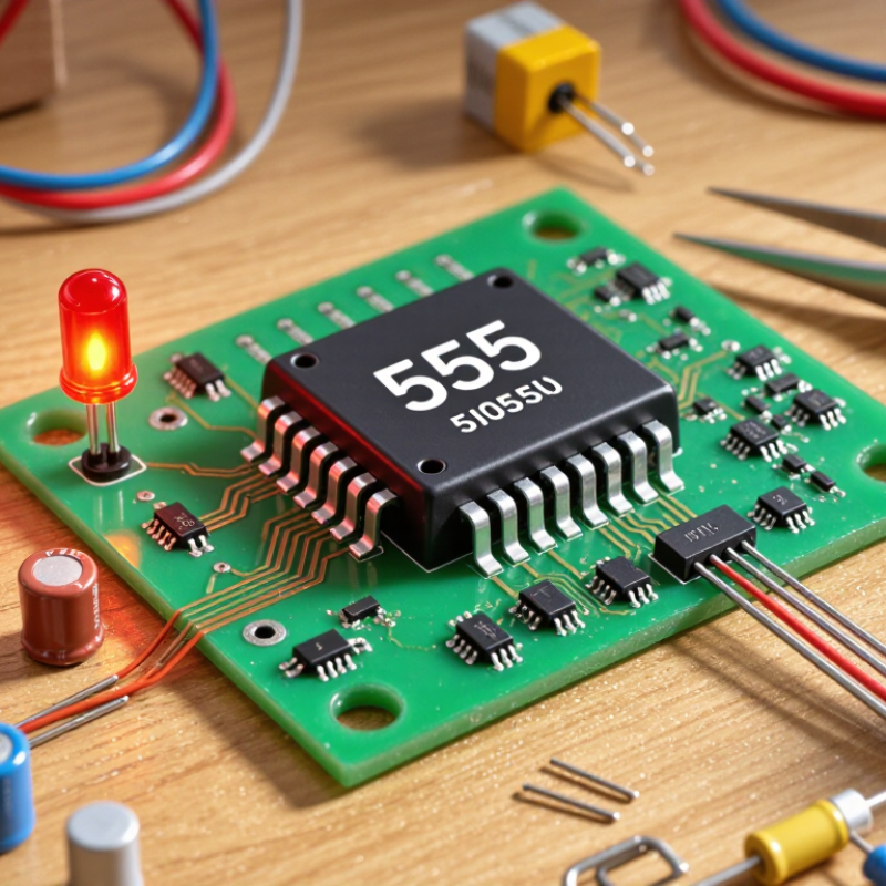
What a 555 Timer IC Does and How It Works
A 555 timer IC turns changing voltage into a useful timing or switching signal. Its operation depends on a capacitor charging and discharging through resistors. Inside the chip, two comparators monitor the capacitor voltage against reference levels near one-third and two-thirds of the supply voltage. A latch remembers which state the circuit should hold. Simple, but clever.
When the capacitor voltage falls below the lower level, the output can switch high. As it charges past the upper level, the output switches low, and an internal discharge transistor helps drain the capacitor. This repeating action creates a square-wave signal, called astable operation.
With a different connection, the circuit can produce one timed pulse after a trigger, known as monostable operation. The exact behavior depends on the external components and circuit layout.
For a practical build, check the IC’s datasheet for its supply range, output-current limits, and timing formulas. A small capacitor may be marked in microfarads, while resistors set how quickly it charges. The math can feel less intuitive than the simple diagram suggests; capacitor tolerance and leakage can shift the timing. Measure the output with a meter or oscilloscope when accuracy matters. A 555 is versatile, not magically precise.
The Main Operating Modes of 555 Timer Circuits
The 555 timer’s main operating modes are monostable, astable, and bistable. In monostable mode, one trigger creates one timed output pulse. Its duration is approximately 1.1 × R × C, so a 100 kΩ resistor and 10 μF capacitor produce about 1.1 seconds. Component tolerances can shift the real result.
Astable mode continuously switches between high and low states, making it useful for flashing LEDs or generating a basic clock signal. A common estimate is f ≈ 1.44/((RA + 2RB)C). In bistable mode, trigger and reset inputs control the output like a simple latch. The standard NE555 datasheet lists a 4.5–16 V operating supply range and output drive capability up to 200 mA. These figures describe that device, not every 555-compatible variant; check the specific datasheet before choosing loads.
Tips: Test timing with the actual capacitor. Electrolytic capacitors can have wide tolerances, and long wires may add noise. I have seen a “one-second” bench setting drift noticeably. That is worth checking. Use a bypass capacitor near the IC’s supply pins, and avoid driving inductive loads directly without suitable protection.
Common 555 Timer Circuit Types and Their Applications
The 555 timer is useful because one device supports several practical circuit types. In astable mode, it repeatedly switches between high and low states, making a simple clock, LED flasher, or tone generator. A resistor and capacitor set the timing; changing either alters the pulse rate. In monostable mode, a trigger produces one timed pulse, useful for debounce circuits and brief relay control. Bistable wiring provides a basic set-reset latch. Keep it simple.
Standard 555 datasheets place the trigger and threshold levels near one-third and two-thirds of the supply voltage. These reference points help explain timing behavior, but component tolerances and supply noise can shift real results. Add a decoupling capacitor close to the IC, especially on a crowded breadboard.
One caveat: a basic 555 circuit is not automatically a precision timer. The Semiconductor Industry Association reported global semiconductor sales of $627.6 billion in 2024, up 19.1% year over year; this market figure provides procurement context, not a forecast for timer circuits.
For buyers, compare operating voltage, output drive, timing stability, and temperature range against the intended application. A tiny pulse generator and a long-delay controller do not need the same component choices. Some designs still work with rough timing, though that trade-off deserves a second look.
How to Choose a 555 Timer Circuit for Your Project
Choosing a 555 timer circuit starts with the job it must do. For a repeating flash or tone, an astable circuit keeps switching without a trigger. A one-shot pulse usually calls for monostable operation. Need two stable states? A bistable arrangement may fit. Keep it simple.
Check the supply voltage and output load before selecting a schematic. A small indicator LED and a relay coil are very different loads; the latter may need a transistor driver. Timing depends on the resistor and capacitor values, so compare the calculated interval with the range your project can tolerate. Electrolytic capacitors can vary noticeably. Measure the real result.
On a workbench, I would begin with common, easy-to-replace components and test the circuit at the intended supply voltage. Add a decoupling capacitor close to the timer’s supply pins to reduce unwanted switching glitches. If the timing changes when the load is connected, inspect the grounding and output stage rather than assuming the timer is faulty. A breadboard can also add loose connections and stray capacitance. It is not perfect. Check the datasheet for the exact device’s operating limits, then choose a circuit whose timing, load, and supply requirements leave some margin.
555 Timer Astable Frequency vs. Timing Capacitor
Estimated output frequency with RA = 10 kΩ and RB = 47 kΩ. Increasing the timing capacitance lowers the oscillation frequency.
Estimates use the astable formula f ≈ 1.44 / ((RA + 2RB) × C). Actual frequency can vary with component tolerances, supply conditions, and circuit loading.
Key Factors for Buying 555 Timer ICs in 2026
When buying a 555 timer IC in 2026, match the device to the circuit rather than choosing by price alone. Check the datasheet for supply-voltage range, temperature limits, package, and output-current ratings. These details vary between bipolar and CMOS versions. A CMOS part often draws less supply current, while a bipolar version may suit a different load or operating setup. Verify the exact requirements.
Small details matter.
For timing circuits, resistor and capacitor tolerances affect the actual delay or frequency. Capacitor leakage can also cause trouble in long-interval designs. If timing accuracy matters, check the stated limits and test the circuit with the intended components. A quick bench test can reveal behavior that a typical-value calculation misses. It is not a substitute for reading the datasheet, though.
Compare operating temperature, input thresholds, and output behavior under your expected load. Confirm that the package fits the board and that the supplier provides clear part identification and traceable documentation. Avoid assuming two devices with similar markings are interchangeable; their limits may differ. My practical bias is to leave margin in voltage and current ratings. It can cost a little more, and sometimes that margin is unnecessary, but a design running near its limits deserves a closer review.
 (780) 669-9420